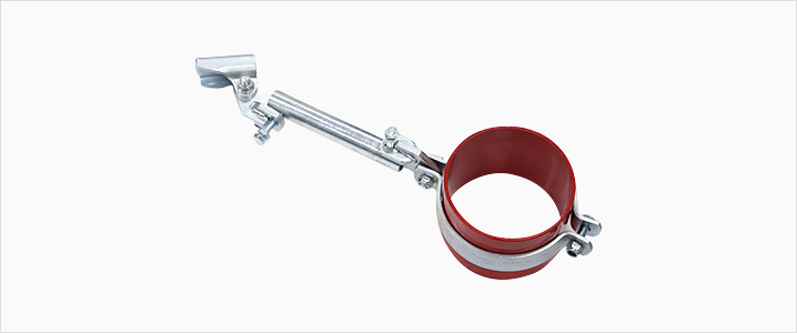
Details and Size
| Specifications | Material | STEEL(Carbon Steel) | ||
|---|---|---|---|---|
| Product Name | Lateral/Longitudinal Bracing | Size | 40A~200A | |
| Product No. | HP-A01 | Installation Angle | 30˚~ 90˚ | |
| KFI Certification No. | Bracing 19-36 | |||
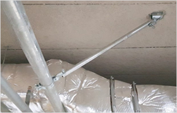
Lateral Bracing Construction Example 1
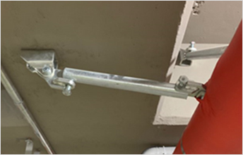
Lateral Bracing Construction Example 2
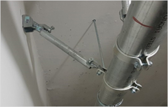
Lateral Bracing Construction Example 3
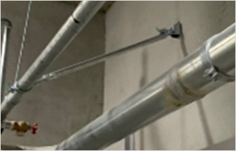
Lateral Bracing Construction Example 4
Lateral Bracing Installation Guidelines
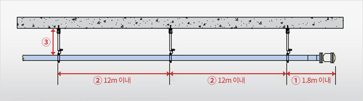
- Install within 1.8m from the end of the main line (water hammer arrestor)
- Maximum interval between bracings should less than 12m
- Possible to exclude when length from the top of the main run to the fixed part (slab, ceiling) is less than 150mm
(Yet, the caliber of the line should under 150mm, possible to exclude spring cooler line only)
For more details, refer to guideline for seismic design standards of fire protection systems (4. Bracing design and safety examination Article “E”)
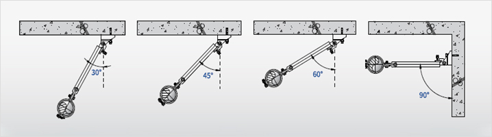
| Rated Load | Installation Angle | Allowable Load by Angle | Applicable Horizontal Force |
|---|---|---|---|
| 7,117N | 30˚~44˚ | 363.11kg ~ 504.44kg | Below 363kg |
| 45˚~59˚ | 513.51kg ~ 622.52kg | Below 513kg | |
| 60˚~89˚ | 628.91kg ~ 726.15kg | Below 628kg | |
| 90˚ | 726.22kg | Below 726kg |